Heat Transfer - Internal and External Extended Tube Surfaces
Please click here to download our Heat Transfer Brochure and Technical Information.
Click or Tap images for more information.
G Finned Tube
L Finned Tube
LL Finned Tube
KL Finned Tube
Wire Finned Tube
Turbulator Inserts
Overview
Tube Fins have developed a range of high performance internal and external surfaces which, when combined, provide a market leading high performance cooling solution.
All of the surfaces have been rigorously tested in the company laboratory and the resulting data, combined with bespoke thermal design software, ensures that the optimum design can be achieved every time.

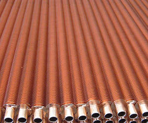
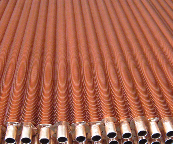
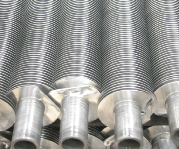
G Finned Tube
High conductivity fin tube ideal for elevated temperature applications.
“G” fin have a helical groove formed in the tube surface with an uplift of metal each side which, when peened back into the fin, grips it securely. This ensures high heat transfer as well as producing a secure mechanical bond.
A wide range of both tube and fin materials are available.
Heat transfer performance can be enhanced by utilising SHE’s (or TFL’s) unique internal solder bonded or pulled in secondary surface/turbulator system.
Manufacturing Details
Aluminium "G" finned tube:
Max. Fin Height - 22.22 mm(0.875") Min. Fin Height - 9.5 mm (0.375") Max. Fin Density - 13.5 FPI (531 FPM) Min. Fin Density - 6.5 FPI (205 FPM) Max. Tube Diam. - 38.1 mm (1.5") Min. Tube Diam. - 15.88 mm (0.625") Max. Tube Length - 15m (49 ft)
Copper "G" Finned Tube:
Max. Fin Height - 19.05 mm(0.75") Min. Fin Height - 6.35 mm (0.25") Max. Fin Density - 12.4 FPI (488 FPM) Min. Fin Density - 6.5 FPI (205 FPM) Max. Tube Diam. - 38.1 mm (1.5") Min. Tube Diam. - 15.88 mm (0.625") Max. Tube Length - 15m (49 ft)
Base Tube Material: Carbon Steel, Stainless Steel, Copper, Copper Alloys
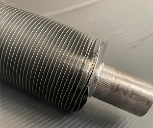
L Finned Tube
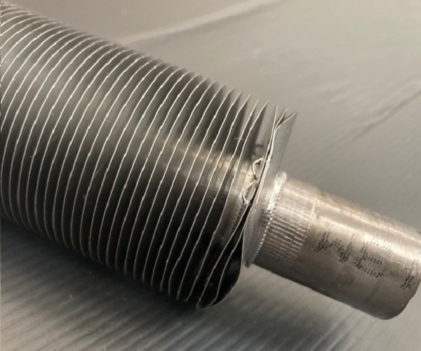
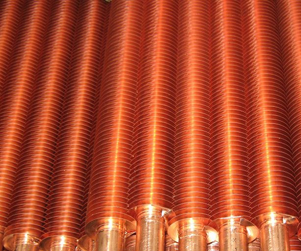
Economically produced fin tube for moderate working temperatures.
“L” finned tube relies on maximum surface contact between fin and tube which is ensured by tension forming fin strip helically around the base tube.
A considerable degree of corrosion protection is given to the tube by the base of the fin. A wide range of both tube and fin materials are available.
Heat transfer performance can be enhanced by utilising SHE’s unique internal solder bonded or pulled in secondary surface/turbulator system.
Manufacturing Details
Aluminium "L" finned tube:
Max. Fin Height - 22.22 mm(0.875") Min. Fin Height - 9.5 mm (0.375") Max. Fin Density - 11 FPI (433 FPM) Min. Fin Density - 6.5 FPI (205 FPM) Max. Tube Diam. - 38.1 mm (1.5") Min. Tube Diam. - 12.7 mm (5/8") Max. Tube Length - 15m (49 ft)
Copper "L" Finned Tube:
Max. Fin Height - 19.05 mm(0.75") Min. Fin Height - 6.35 mm (0.25") Max. Fin Density - 11 FPI (433 FPM) Min. Fin Density - 6.5 FPI (205 FPM) Max. Tube Diam. - 38.1 mm (1.5") Min. Tube Diam. - 9.5 mm (5/8") Max. Tube Length - 15m (49 ft)
Base Tube Material: Carbon Steel, Stainless Steel, Copper, Copper Alloys, Titanium
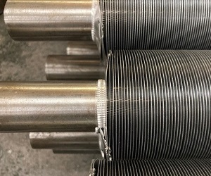
LL Finned Tube
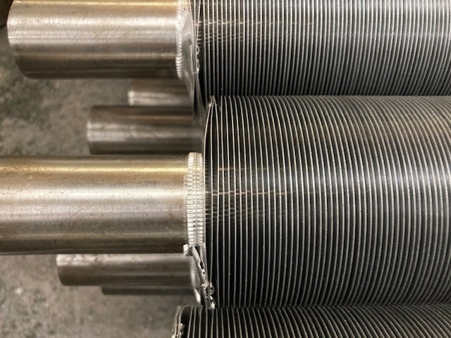
Double “L” fin is used on applications requiring additional corrosion protection to the surface
of the base tube. It is produced similar to “L” fin but has a wider fin base which is overlapped
during the winding process.
Operating temperature is a little higher than for L fin.
A wide range of both tube and fin materials are available.
Heat transfer performance can be enhanced by utilising SHE’s (or TFL’s) unique internal solder bonded or pulled in secondary surface/turbulator system.
Operating temperature is a little higher than for L fin.
A wide range of both tube and fin materials are available.
Heat transfer performance can be enhanced by utilising SHE’s (or TFL’s) unique internal solder bonded or pulled in secondary surface/turbulator system.
Manufacturing Details
Aluminium "LL" finned tube:
Max. Fin Height - 22.22 mm(0.875") Min. Fin Height - 6.35 mm (0.25") Max. Fin Density - 15.8 FPI (622 FPM) Min. Fin Density - 8 FPI (315 FPM) Max. Tube Diam. - 38.1 mm (1.5") Min. Tube Diam. - 9.5 mm (5/8") Max. Tube Length - 15m (49 ft)
Copper "LL" Finned Tube:
Max. Fin Height - 19.05 mm(0.75") Min. Fin Height - 6.35 mm (0.25") Max. Fin Density - 12.4 FPI (488 FPM) Min. Fin Density - 8 FPI (315 FPM) Max. Tube Diam. - 38.1 mm (1.5") Min. Tube Diam. - 12.07 mm (5/8") Max. Tube Length - 15m (49 ft)
Base Tube Material: Carbon Steel, Stainless Steel, Copper, Copper Alloys, Titanium
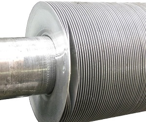
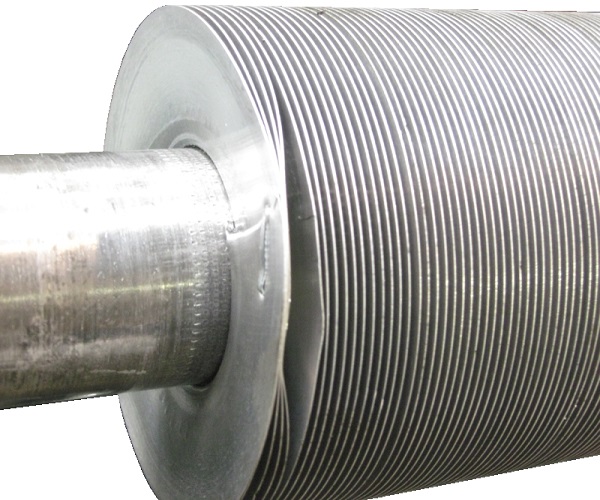
KL Finned Tube
Economically produced fin tube which can operate at temperatures between LL and G type.
“KL” finned tube relies on maximum surface contact between fin and tube which is ensured by tension forming fin strip helically around the pre knurled tube offering an improved bond and heat transfer.
A considerable degree of protection is given to the tube by the base of the fin.
A wide range of both tube and fin materials are available.
Heat transfer performance can be enhanced by utilising SHE’s (or TFL’s) unique internal solder bonded or pulled in secondary surface/turbulator system.
Manufacturing Details
Aluminium "KL" finned tube:
Max. Fin Height - 22.22 mm(0.875") Min. Fin Height - 9.5 mm (0.375") Max. Fin Density - 11 FPI (433 FPM) Min. Fin Density - 6.5 FPI (205 FPM) Max. Tube Diam. - 38.1 mm (1.5") Min. Tube Diam. - 12.7 mm (5/8") Max. Tube Length - 15m (49 ft)
Copper "KL" Finned Tube:
Max. Fin Height - 19.05 mm(0.75") Min. Fin Height - 6.35 mm (0.25") Max. Fin Density - 11 FPI (433 FPM) Min. Fin Density - 6.5 FPI (315 FPM) Max. Tube Diam. - 38.1 mm (1.5") Min. Tube Diam. - 9.5 mm (5/8") Max. Tube Length - 15m (49 ft)
Base Tube Material: Carbon Steel, Stainless Steel, Copper, Copper Alloys, Titanium
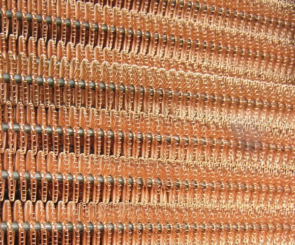
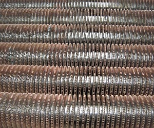
Wire Finned Tube
Wire finned tube is a high efficiency tube consisting of a series of elongated wire loops, spirally
wound on to the tube wall and held in position with a binding wire at the base of the loops. The
loops and binding wire are then soft soldered to the tube wall to give a metallic bond between
the wire fins and the tube.
The loop density and wire diameter can be varied to give the optimum surface for specific heat transfer and pressure drop requirements.
The wire loop secondary surface gives these finned tubes excellent heat transfer characteristics because of its ability to promote turbulence in the fluid passing over it and thereby reducing the tendency for boundary layer formation.
A wide range of both tube and wire materials are available.
Heat transfer performance can be enhanced by utilising SHE’s (or TFL’s) unique internal solder bonded or pulled in secondary surface/turbulator system.

Manufacturing Details
Wire Details:
Max. Fin Height - 19.05 mm(0.75") Max. Tube Diam. - 31.8 mm (1.25") Max. Tube Length - 9m (30 ft)
Base Tube Material: Carbon Steel, Stainless Steel, Copper, Copper Alloys
Standard Wire Material: Stainless Steel, Copper
Turbulator Inserts
In plain tubes, fluid flow is essentially laminar, and skin friction hinders the flow of fluid in
contact with the tube wall. At the same time this outer fluid cools faster and becomes more
viscous, further retarding the flow. The result is a build-up of concentric fluid layers, with
the hot fast-flowing inner fluid surrounded by cooler, slower flowing outer fluid. These outer
layers-boundary layers-insulate the hotter fluid from the cool tube wall resulting in a very
low heat transfer rate.
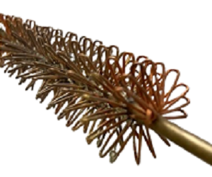
Wire loop inserts eliminate boundary layers by completely disrupting laminar flow.
The insert is made from a continuous wire which is formed into loops. The loops are spirally wound around a small diameter rod and solder bonded in place.When installed in a tube the wire loops keep the fluid in a constant state of turbulence, preventing the formation of thick boundary layers and continually presenting hot fluids to the cool tube wall.
Even with the viscous fluids at low velocities the wire loop insert provides extremely efficient mixing giving vastly improved heat transfer. Any pressure loss experienced is more than compensated for by the increased heat transfer rate.
These wire loop inserts can be solder bonded into any externally finned tube with a variety of geometries and densities to suit particular heat transfer and pressure loss requirements.
